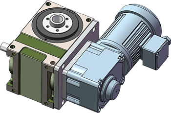
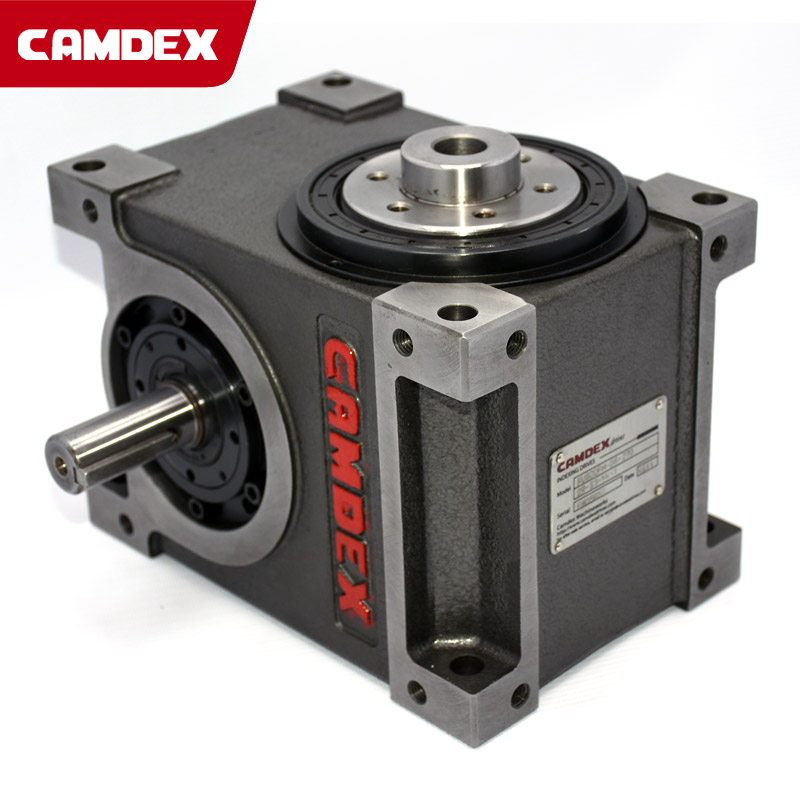
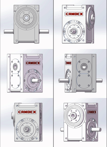
DFH series cam indexer
This series of models have the same characteristics as the DF flange type cam indexer, but the difference is the hollow output form. The hollow output shaft can pass through the power cord, air pipe, water pipe, etc., which is convenient for the design and use of the automation system. The aperture size of the hollow indexer varies according to the size of the model.
Product Details
|
DFH series specifications |
Details |
|
Distance between out and in shaft/mm |
45 |
60 |
70 |
80 |
100 |
110 |
125 |
140 |
180 |
|
Hollow shaft diameter |
8 |
15 |
18 |
25 |
25 |
30 |
35 |
40 |
50 |
|
Number of divisions (number of stations) |
2,3,4,5,6,8,10,12,15,16,20,24,30,32,36,40,48,60,72 |
|
Drive angle (deg) |
90°,120°,150°,180°,210°,240°,270°,300°,310°,330°,360° |
|
Input shaft speed (rpm) |
0-600 (determined according to customer needs) |
Technical Parameters
|
Item |
Sym-bol |
Unit |
Distance between out and in axis |
|
45DFH |
60DFH |
70DFH |
80DFH |
83DFH |
100DFH |
110DFH |
140DFH |
180DFH |
|
Allowable thrust load on output shaft |
C1 |
kgf |
80 |
180 |
220 |
220 |
330 |
400 |
500 |
730 |
1200 |
|
Allowable radial load on output shaft |
C2 |
kgf |
72.5 |
150 |
220 |
220 |
420 |
450 |
550 |
860 |
1500 |
|
Allowable torque on output shaft |
Ts |
kgf-m |
Refer torque table |
|
Allowable thrust load on input shaft |
C3 |
kgf |
85 |
100 |
150 |
210 |
350 |
300 |
360 |
440 |
590 |
|
Max. repetitive bending force on input shaft |
C4 |
kgf |
75 |
95 |
110 |
190 |
260 |
220 |
290 |
560 |
1045 |
|
Max. repetitive torque on input shaft |
C5 |
kgf-m |
4 |
6 |
9.5 |
18.5 |
25 |
26 |
32 |
75 |
147 |
|
GD2 of input shaft (Note1) |
C6 |
kgf-m2 |
3.2 x 10⁻⁴ |
1.9*10-3 |
6*10-3 |
9*10-3 |
9*10-3 |
4*10-3 |
2.8*10-3 |
0.11 |
0.39 |
|
Indexing accuracy |
|
sec. |
±60 |
±45 |
±30 |
±30 |
±30 |
±30 |
±30 |
±30 |
±30 |
|
Weight |
|
kg |
7 |
13 |
18 |
32 |
26.5 |
50 |
65 |
90 |
220 |


